Hardware Setup
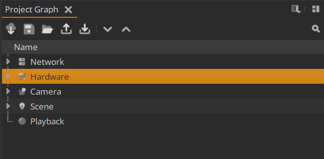
Once you have done the Network Setup steps, you can create your Hardware config by going to Project Graph > Hardware.
Creating Outputs
Firstly, add and define outputs for each RenderNode.
| 1. | Go to Project Graph > Hardware > Outputs. |
| 2. | Select the + button to add an Output. |
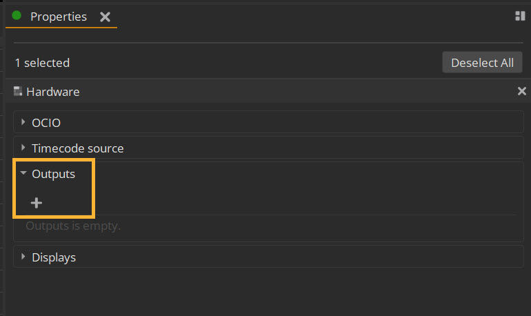
| 3. | Use the options to configure: |
• You'll need to define the size of your output display for each RenderNode using the Viewport properties. For reasons around sync, this output size should be the complete size of your display even if you’re only using a subsection of that display on the wall. If you are using a subsection this can be defined in the output mapping in a later step.
• It's recommended to tick the box to set the window to be Borderless, which will also help sync.
• It’s also recommended to leave the other Output settings as they are by default, Swap interval to “Every Frame” and Enable framelock ticked.
Further information about each option can be found at Outputs Controls.

Creating Displays
Once you’ve got an output to represent the window within the RenderNode, you then need to create a representation of the physical wall under Displays.
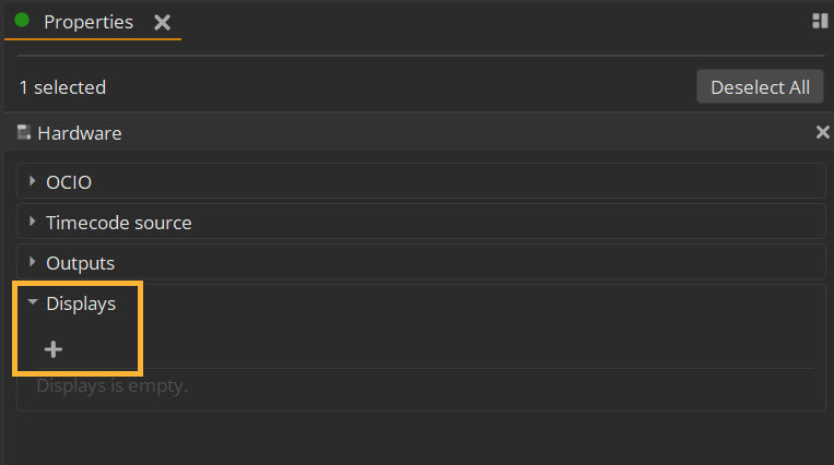
| 1. | Go to Project Graph > Hardware > Displays. |
| 2. | Select the + button to add a Display. |
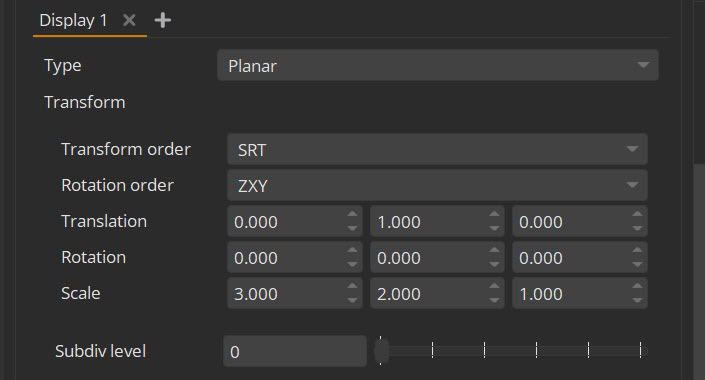
| 3. | Here you can load any existing FBX with submeshes, or alternatively create simple planar meshes manually. The scale of the meshes should match the scale within any USD file you may load but for simplicity it’s usually easiest to use meters as the scale. |
Further information about each of the options can be found at Displays Controls.
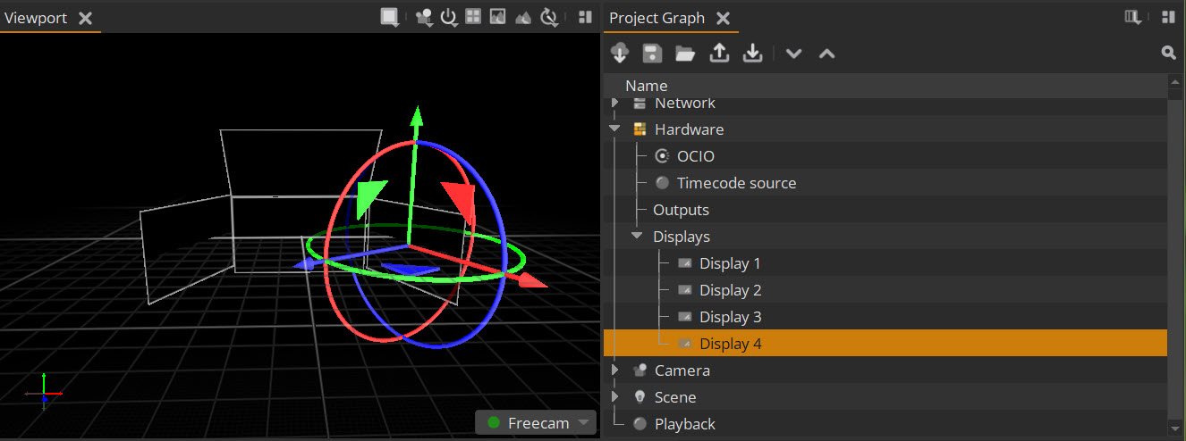
| 4. | Once each Display has been created, you can translate, rotate or scale directly via the Properties panel. You can also translate and rotate in the Viewport using the handles if you select the display within the Project Graph, as below. Note that you cannot yet select the display from within the Viewport. |
| 5. | Once the physical wall has an accurate mesh representation, you can set up the output mapping for each Display under Project Graph > Hardware > Displays > Output Mapping. |
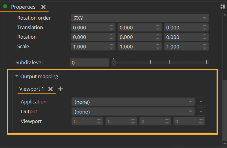
• In the Application dropdown, define which RenderNode is going to do the rendering for the selected parent display.
• In the Output dropdown, select which output to use.
• The Viewport property is where you can define which part of your output is rendering for this display. This is useful for when the required window is a subsection of your total output (i.e. smaller than your Windows display) or if you have multiple displays per output. If you leave these values as zero, it will render the entire output you have defined in your Output properties.
Further information about each option can be found at Output Mapping Controls.
Note: Before a RenderNode window is connected via output mapping, in the Image Viewer there will be a message stating it’s waiting for connection. This will disappear when it’s connected.
Additional Hardware Settings
The above will define the main settings needed for a hardware setup. However, there are additional options accessed from the hardware section within the Project Graph such as the OCIO Color Management settings and Timecode Source.